Remote Battery Installation
“Remotely Connected”
by Dennis Overholser Painless Performance
Gizmos to gadgets, there are countless numbers of electrical options we now put in our classic rides. Not to many years ago a radio was about the only option, now air conditioning, power this and power that is the norm. In dealing with all the power needed a battery is still the center piece of the electrical system and where to mount the battery sometimes becomes a challenge. Keeping the engine compartment clean is sometimes a priority and to do so the battery is usually relocated. In a street rod or a classic, the solution is simple, the trunk.
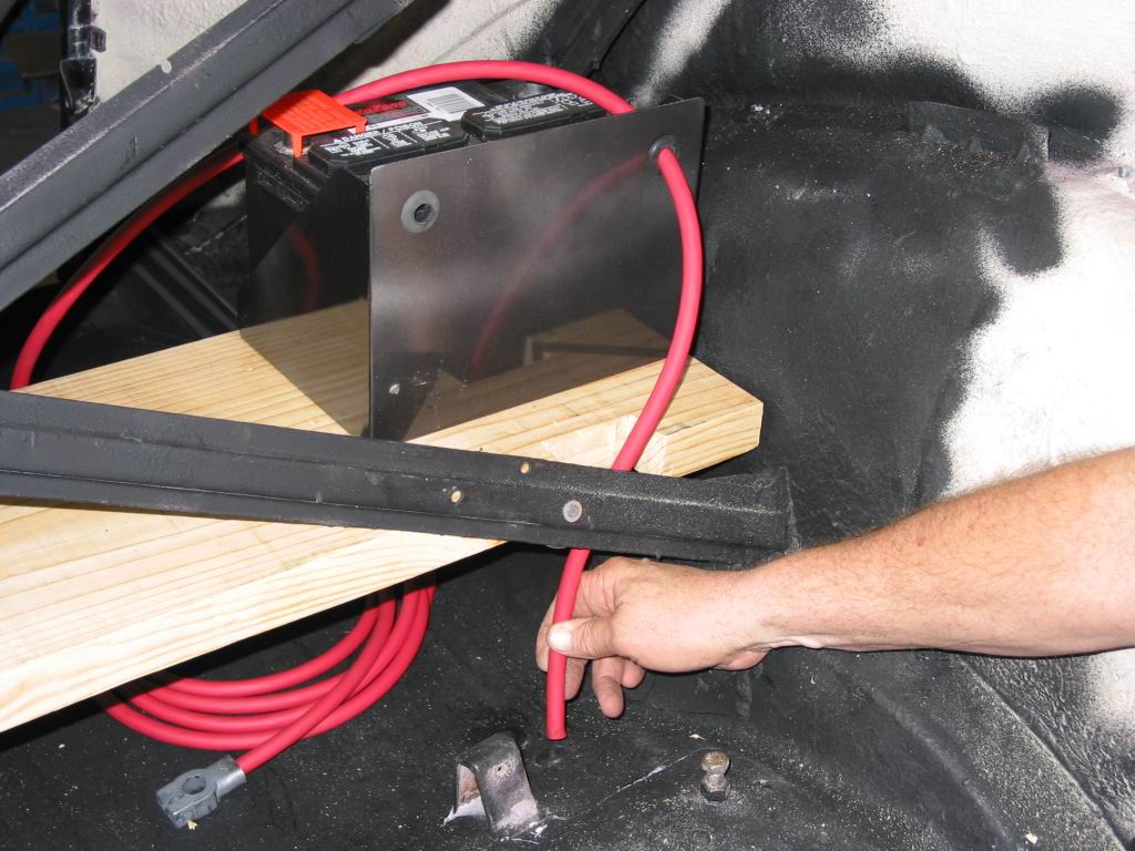
The same is true for the 37 Plymouth that Jerry Wallace is building. There is no room under the hood or floor pan so the trunk was the best solution. Jerry built a shelf to mount the battery box he received from Mr. Street Rod in Simi Valley Ca. The shelf also would provide a place for a tool box later. A battery cable kit from Painless Performance would be all Jerry needs to get power to the rest of the car.
Once the battery box was mounted, the cables were routed, cut to length and terminals were installed. The Painless kit, which has #1 high strand cables came with terminals as well as heat shrink to seal and protect the crimped on cable ends. Ground cables were made to connect the body to the frame as well as the frame to the engine/transmission. The cables were installed with star washers to insure good contact at each grounding point.
With the box, battery and cables installed, Jerry will have many years of safe dependable service.
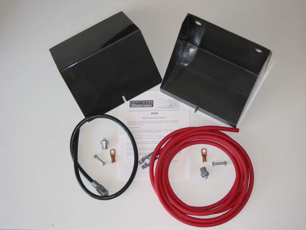 | 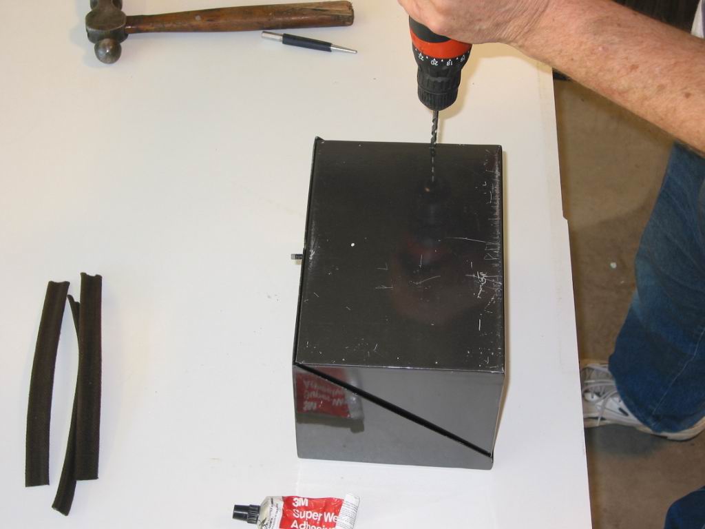 | |
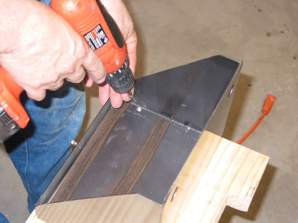
| The battery box and cable kit are ready for installation. All required copper terminals as well as simple instructions are included | Jerry didn’t want the box to move around while driving so he drilled some holes in the bottom which will allow it to be mounted with screws | |
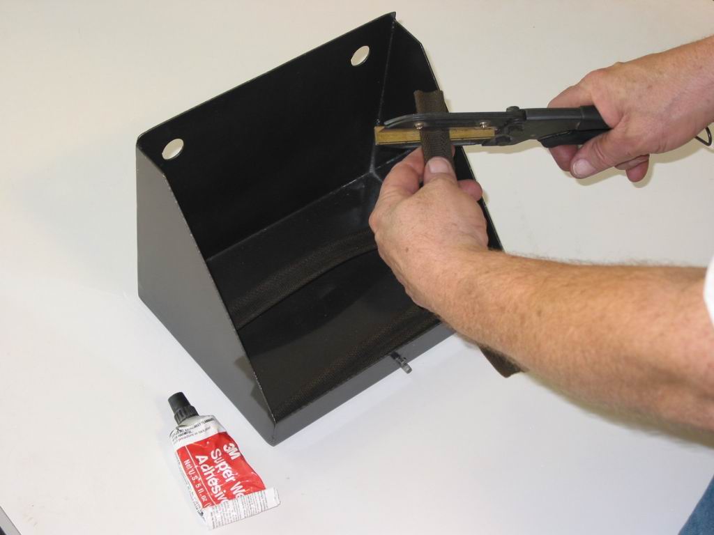 | 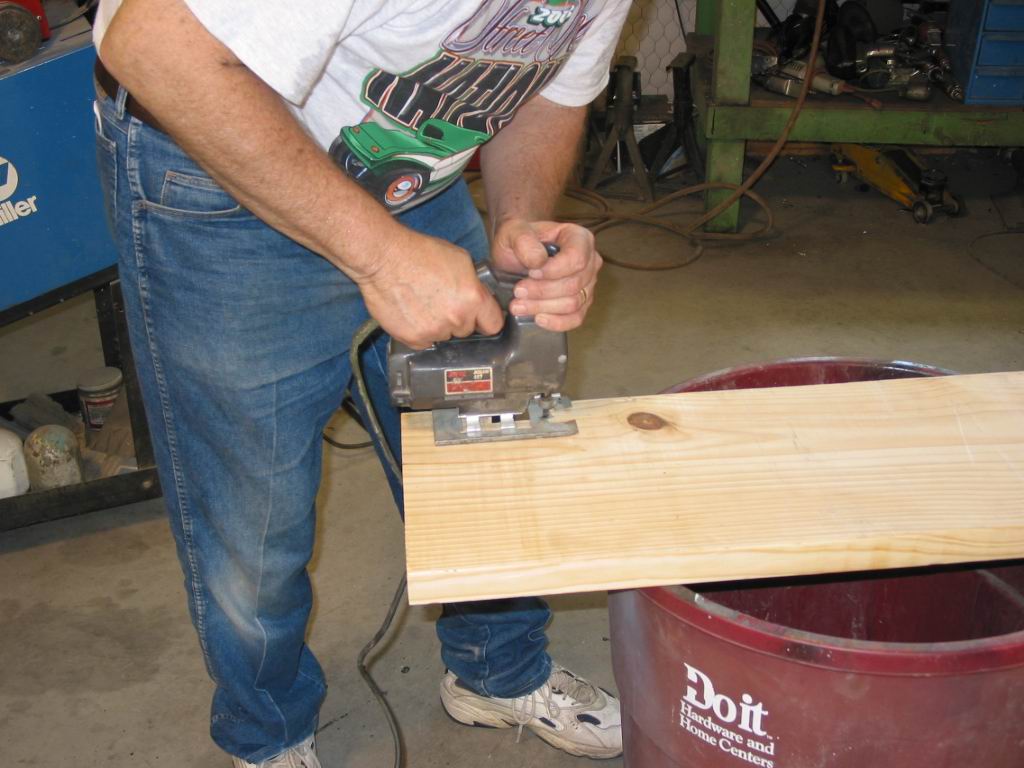 | |
| Some left over hood welting was cut and glued to the bottom inside of the box to protect the battery from the mounting screws. | The shelf was measured and cut to size. A notch was also cut out to allow the cables to pass down to the floor openings. | |
 |  | |
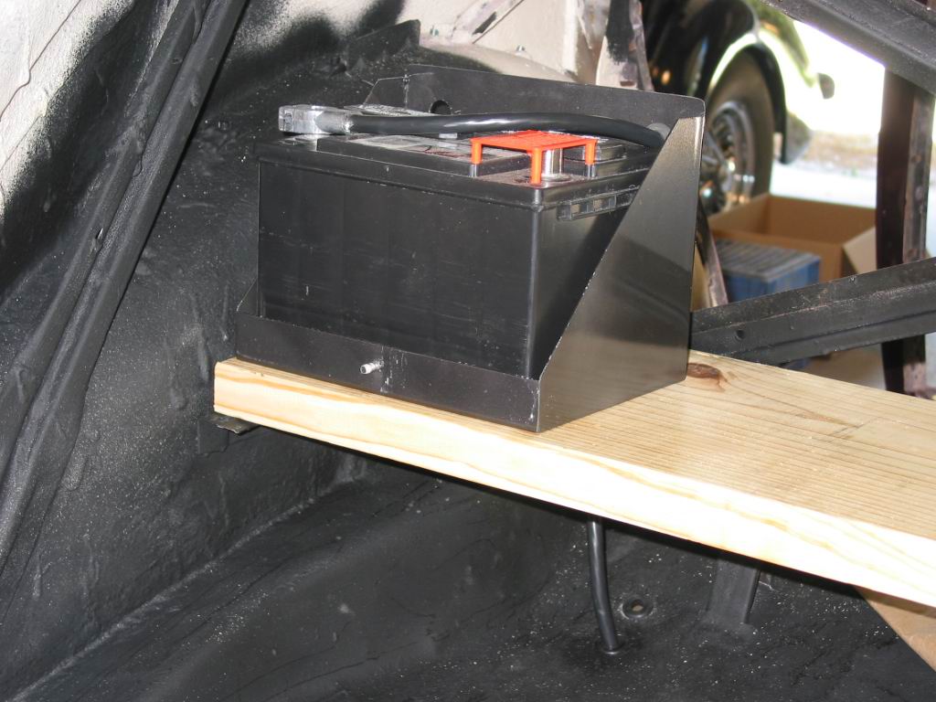
| The box is now mounted to the shelf | Two holes are drilled through the trunk floor pan for the cables. Care was taken to insure that nothing was under the floor area that could be damaged. | |
 | 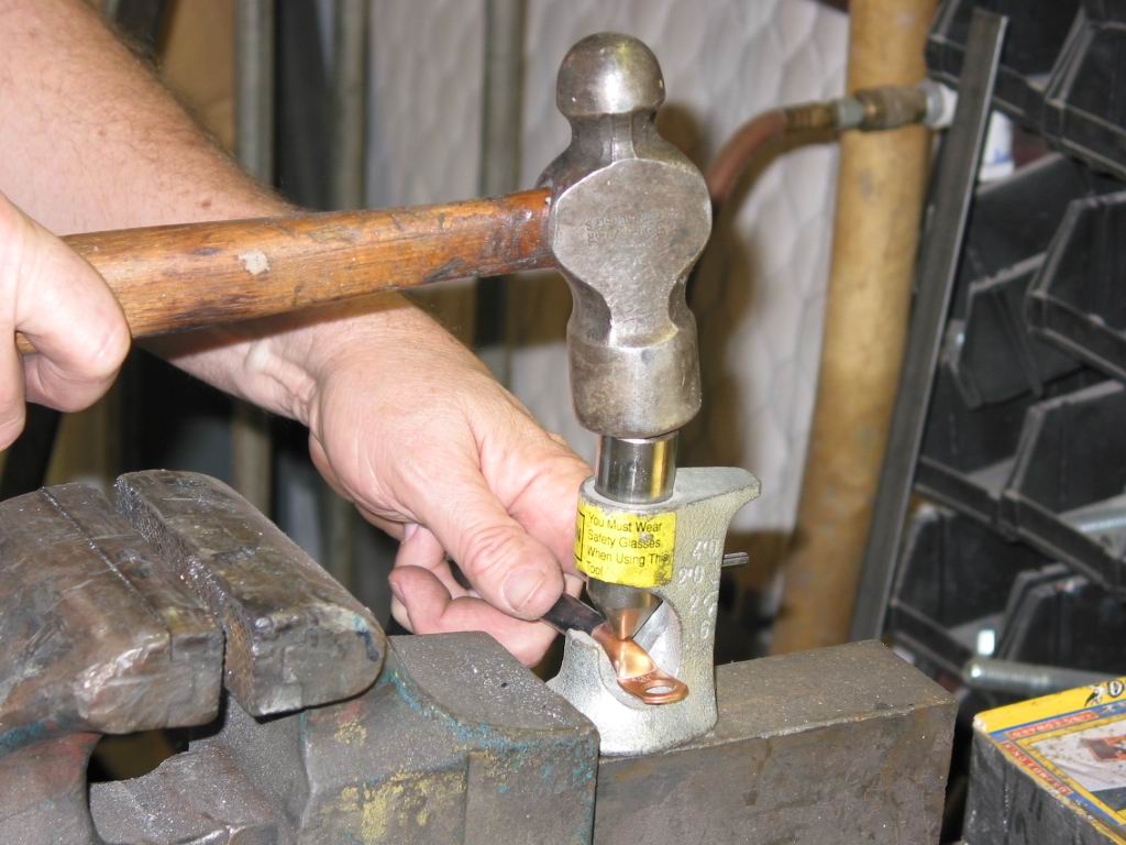 | |
| The shelf in place, the negative cable was routed through the floor and checked for proper length | A hammer style crimper was used to install the ring terminal on the negative cable. A crimp is better than solder in most cases due to possible extreme heat generated by the starter | |
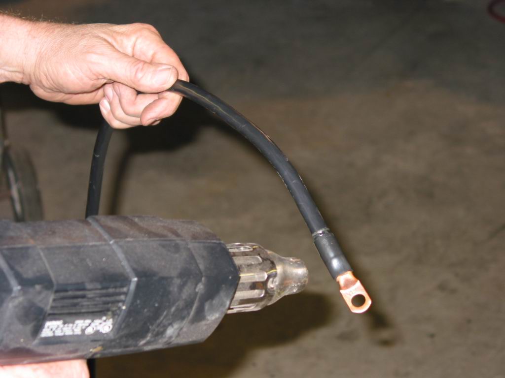 |  | |
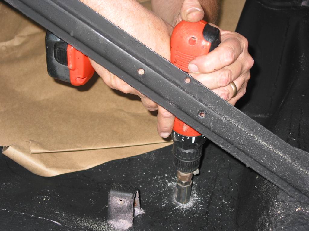
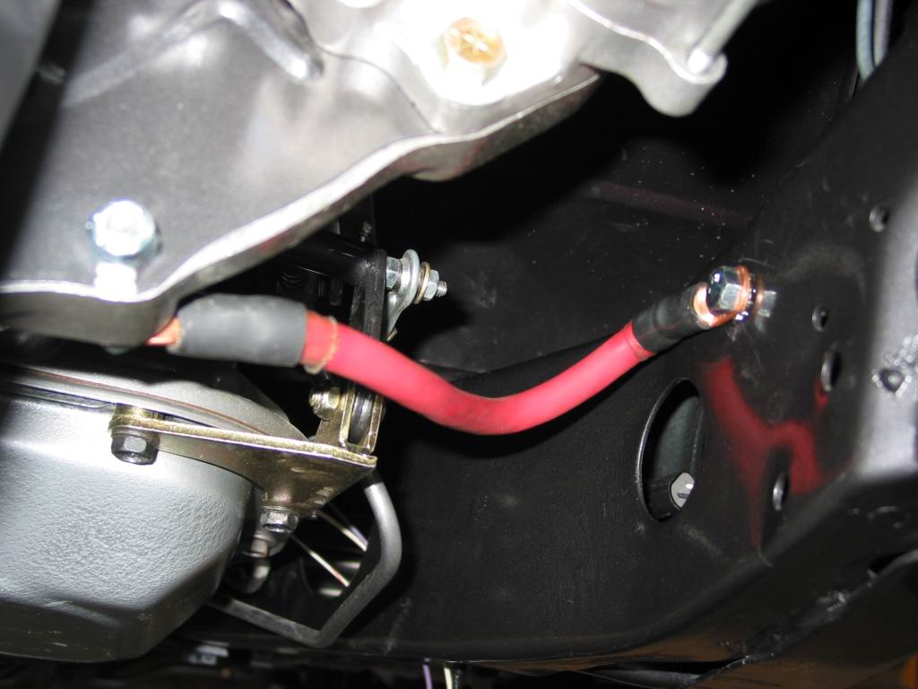
| The terminal now installed, a piece of heat shrink with glue inside is installed. The glue will protect the cable from moisture and corrosion. | The positive cable is routed through the floor pan and down the frame rail | |
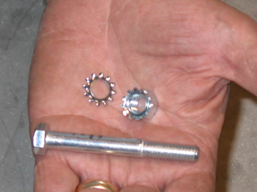 | 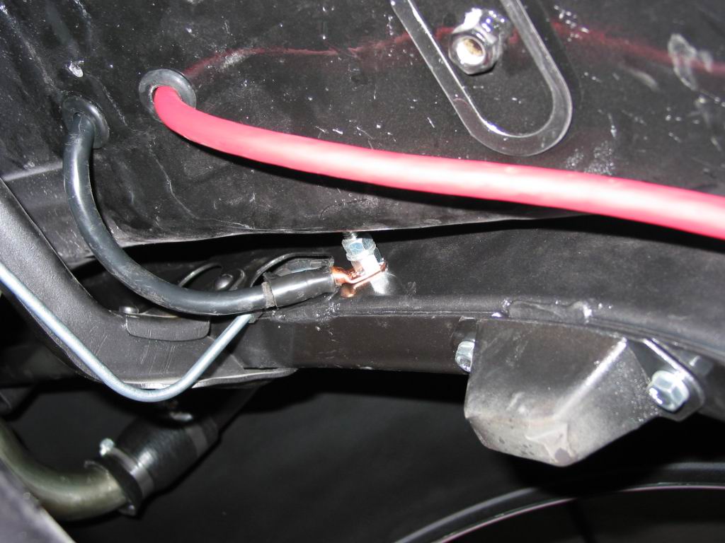 | |
| New hardware was chosen from the local parts store. Star washers were used to insure good contact between the terminal and the frame | Rubber grommets were installed around the cables to prevent any future abrasion and possible shorts | |
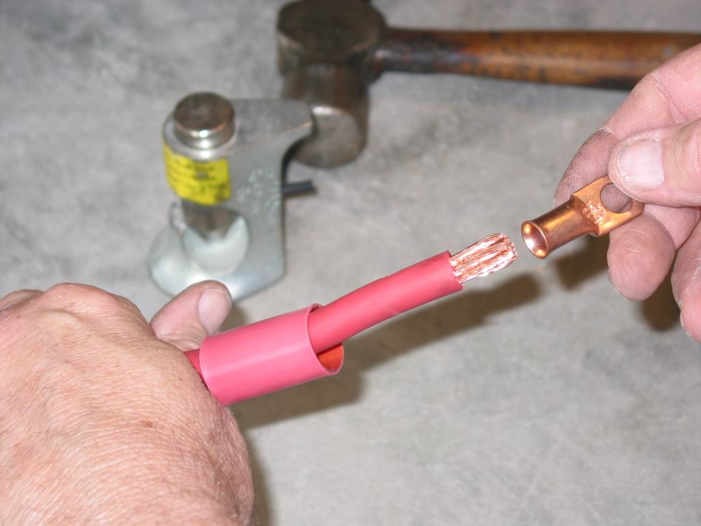 | 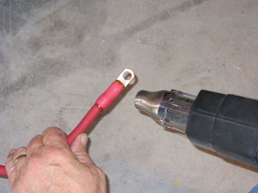 | |
| The positive cable was routed and cut to length. The terminal and heat shrink are ready to be installed | Once crimped, the heat shrink was installed over the terminal | |
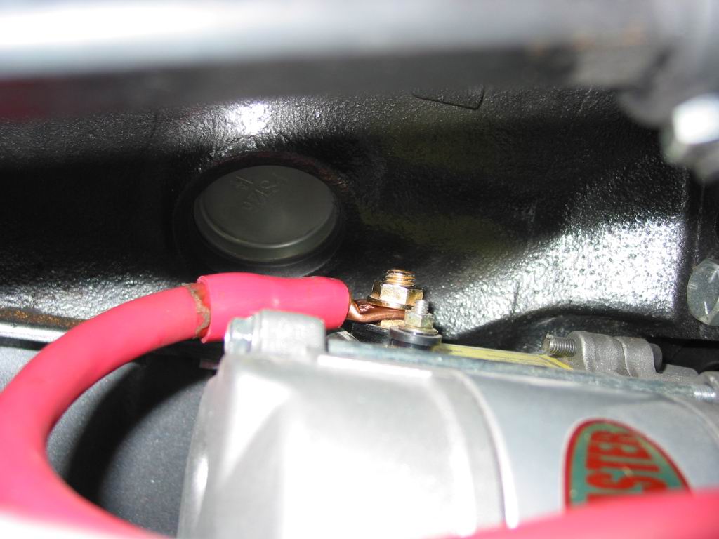 |  | |
| The finished cable was routed and attached to the starter solenoid | A short piece of extra cable was terminated and covered to make a ground strap from the transmission to the frame. Once again star washers were used to make a good connection | |
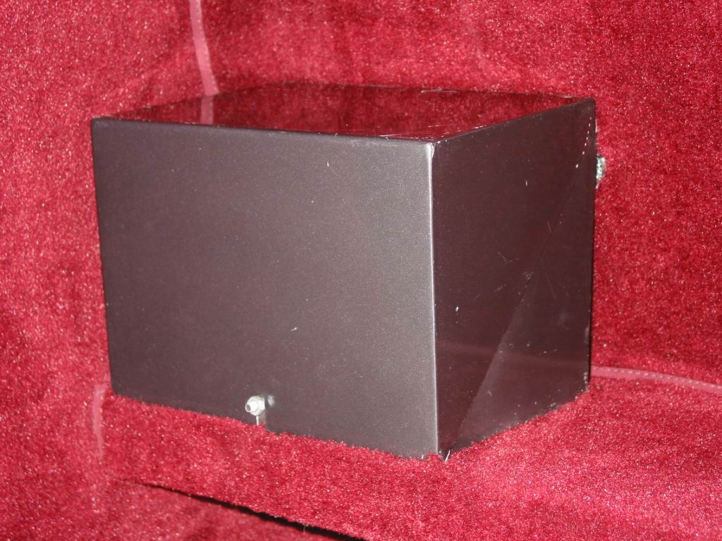 | 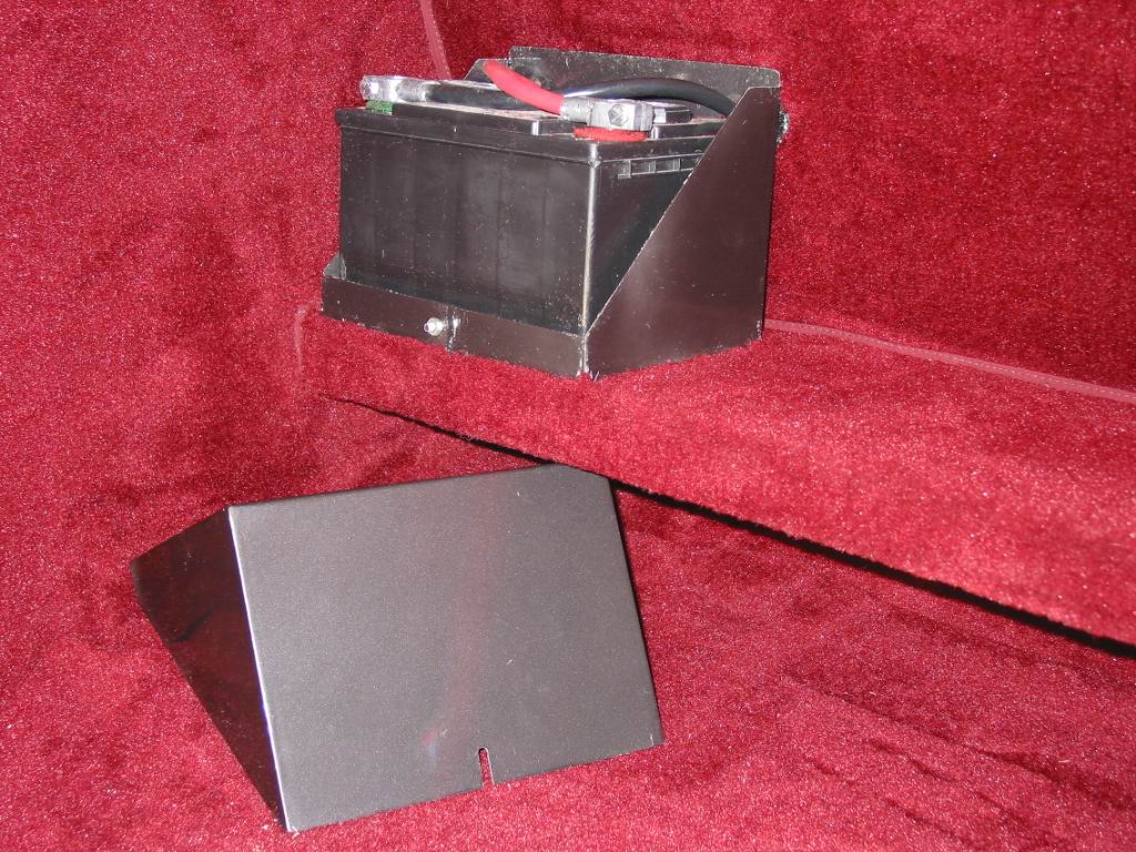 |
The finished installation. The cover installed protects the battery from articles placed in the trunk as well as making the battery attractive.
Article Provided by : Painless Performance Wiring