Old Style Ignition By: Dennis Overholser Painless Performance
Old school styling is making a come back. Wide whites, three deuces and flat black paint is becoming common place again. Car enthusiasts want to relive their past and have more good times like they remember. The art of car building has changed dramatically over the past 40 years but not necessarily the themes. Wanting that original look is still a high priority for some and will do what ever it takes to maintain it.
Electrical systems and switches are always a challenge in keeping the original look. Converting from 6 volt systems to 12 volt has become common but sometimes the original switches can be tricky to use. The original ignition switch, like the one in this 1939 Ford, will not carry the amount of current required by today’s creature comforts as well as having segregated circuits for ignition and accessories. These switches can still be used by using some relays to create separate circuits for ignition and accessory devices. The starter is another item that can be a challenge. The original 6 volt starter solenoid used a ground to activate it where most new 12 volt solenoids require a 12 volt input for activation. Once again, by using a relay, the original starter button, which creates a ground when depressed, can be used to trigger a 12 volt activation input to the starter solenoid.
Electrical systems are one of the most depended on in a vehicles operation. Up grading is a must when adding air conditioning, power windows and locks and don’t forget that big new electric fan. Cutting corners on wiring can cost many times over in problems down the road.
Old style looks will always be in demand, all we have to do is figure out how to keep them and still have the creature comforts we have become accustomed
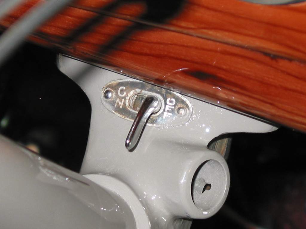 | 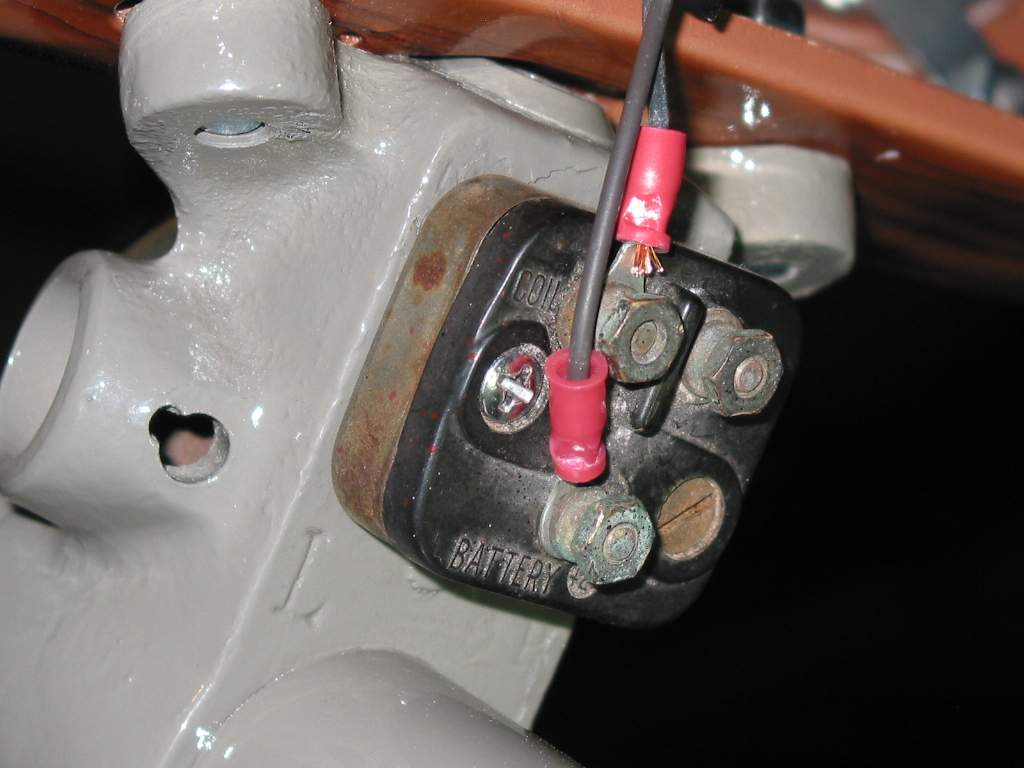 | |
| 1 This original 1939 ignition switch has it’s own style. They were only off or on but did have, in their day, a decent current carrying capacity. They work great for switching grounds for relay activation. | The back of the ignition switch reveals only two terminal posts. Battery input and ignition output. Shown is a ground wire that is attached to the dash ground and the ground wire for the ignition and accessory relays | |
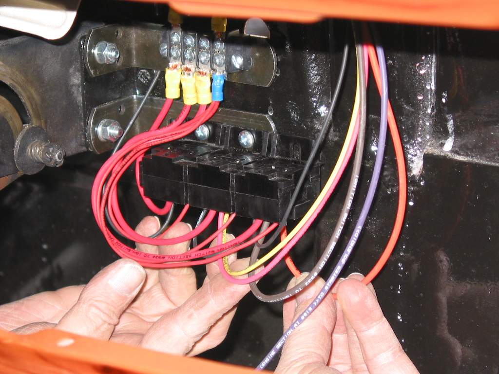 | 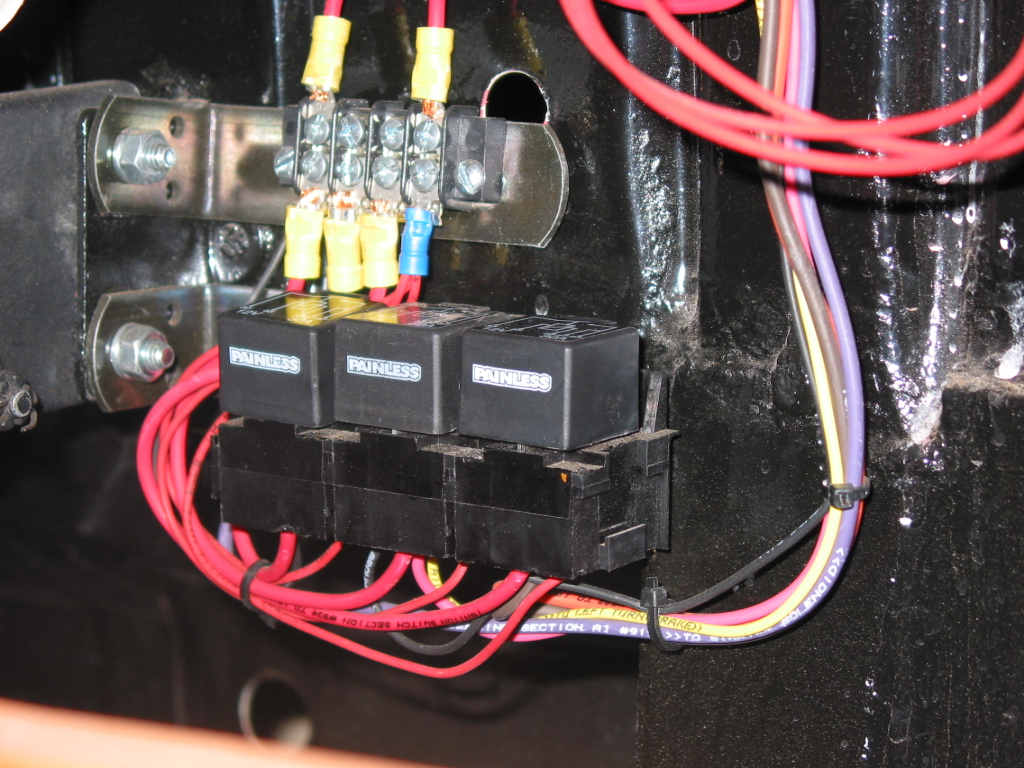 | |
| For powering ignition, accessory and starter circuits, relays are used. These three relay bases are attached up under the dash and will be activated by the original ignition switch and starter button. Each of these switches create a ground which will activate the relays | The relays are provided power from the fuse block input wire that is attached to the top of the buss bar. When the relays are activated, 12 volts is applied to each output circuit Caution should be taken not to demand more power in the accessory and ignition circuits than the relays can safely handle. Need more power, add more relays. | |
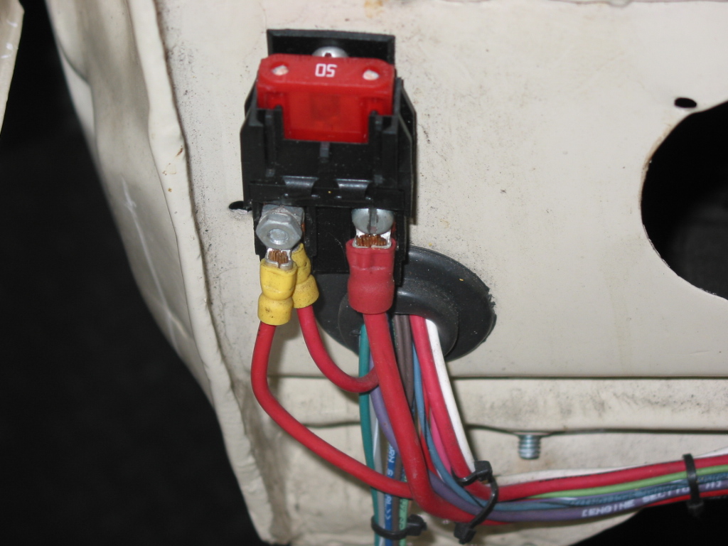 | 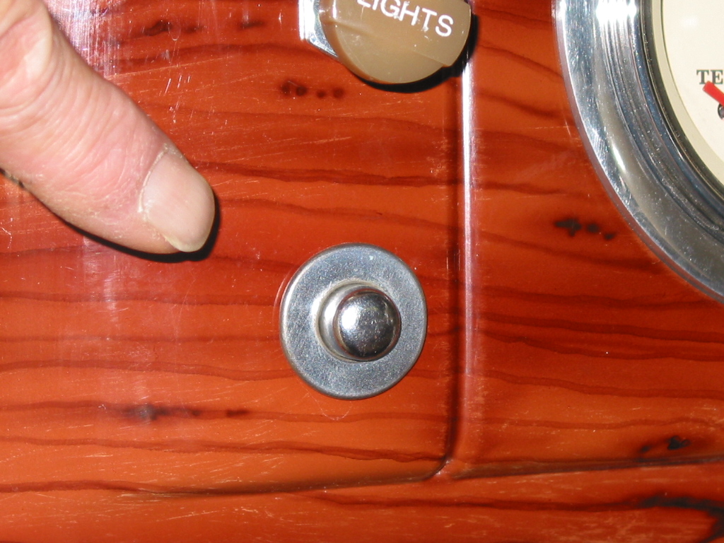 | |
| Another option for providing power for the relays is to route a heavy gauge wire to the maxi fuse. Always attach it to the fused side for overload protection | The starter button is another grounding switch. It’s old style looks gives class to the dash. | |
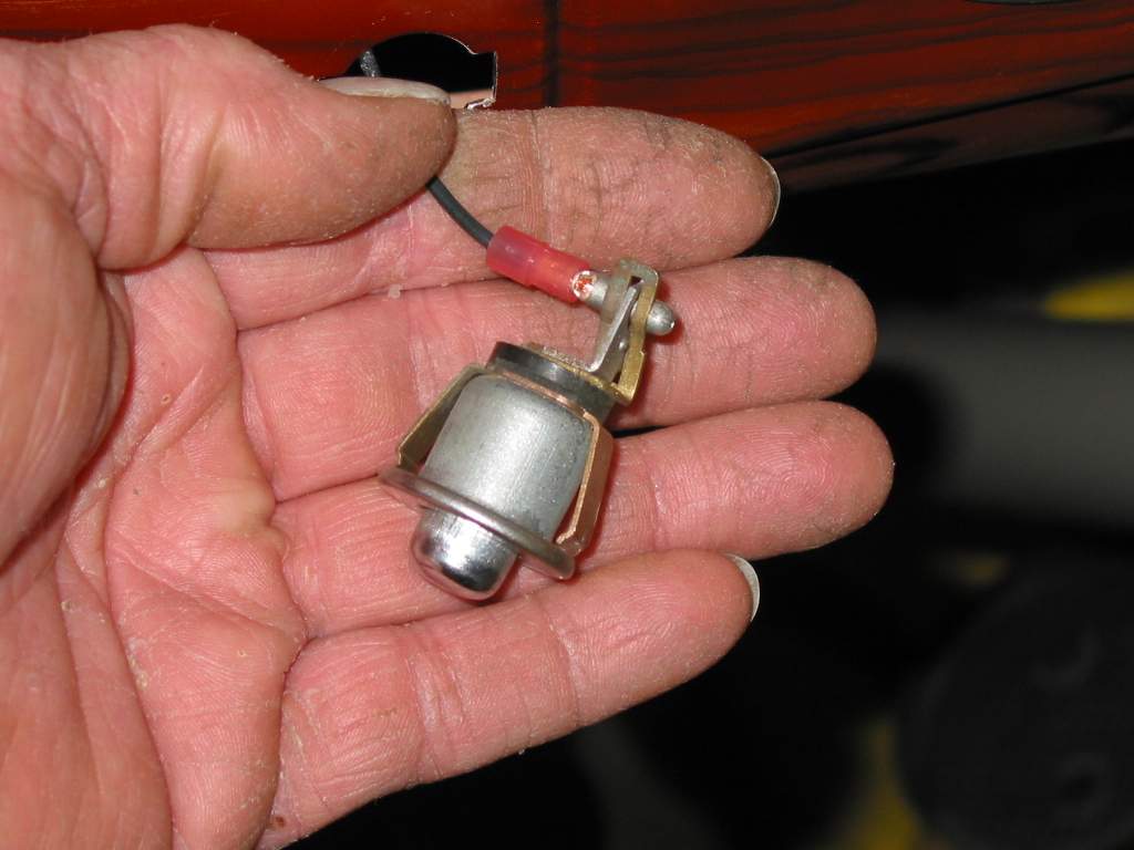 | 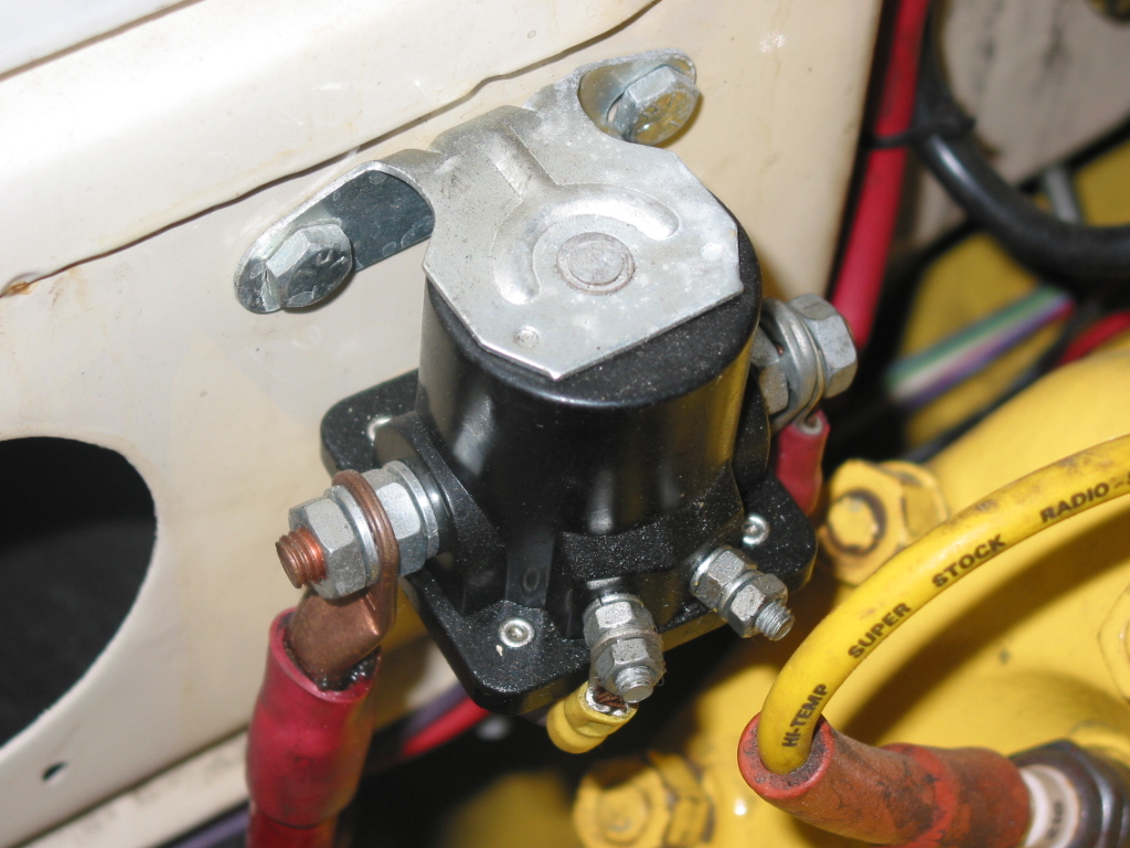 | |
| With the switch removed from the dash, it reveals the one ground wire for activation. The original harness had a bullet terminal similar to the new one shown | The new solenoid has four terminal posts. One large for battery input, one large for output to the starter. The small terminal post on the left with a wire attached is for solenoid activation, the other post, if your solenoid is so equipped, is for ignition bypass when using a conventional point style distributor |
In summary, when the starter button is depressed it creates a ground for the relay. The relay closes an internal circuit allowing battery current to flow through and on to the starter solenoid for activation. When the solenoid is activated it allows battery current to flow to the starter motor causing it to turn starting the engine.
This article was provided by: Painless Performance Wiring