Installing a Fuel Gauge and Sender
By: Jim Clark, the Hot Rod M.D.
Modern high-mpg cars have large fuel tanks and experience extended-range between fill-ups. Old hot rods with small fuel tanks and big gas-guzzling engines require more frequent fuel stops. This makes an accurate fuel gauge more important when embarking on the open road. So this often overlooked device takes on a more important role.

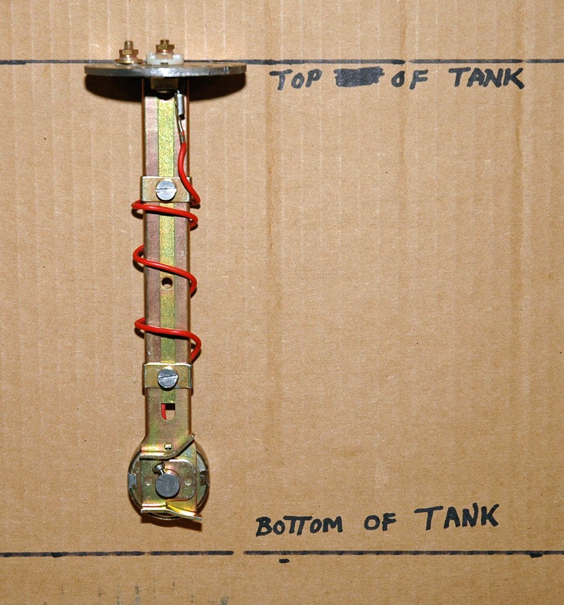


I had to use the sending unit supplied with my VDO fuel gauge because it registers empty at 10 ohms and full at 180 ohms, the same as new VDO gauge senders. The standard aftermarket senders now measure the fuel capacity at 33 ohms empty and 240 ohms at full. Bolt pattern was rotated slightly to match the six-hole pattern on my stock '32 tank. Large hole is for fuel pickup tube.

Fuel pickup tube was fabricated by silver-soldering a length of 3/8th fuel line to a 3/8th pipe thread / hose barb 90° fitting. Was cut to length and fitted with Ford in-tank nylon mesh filter from van / F-100 pickup (not shown).
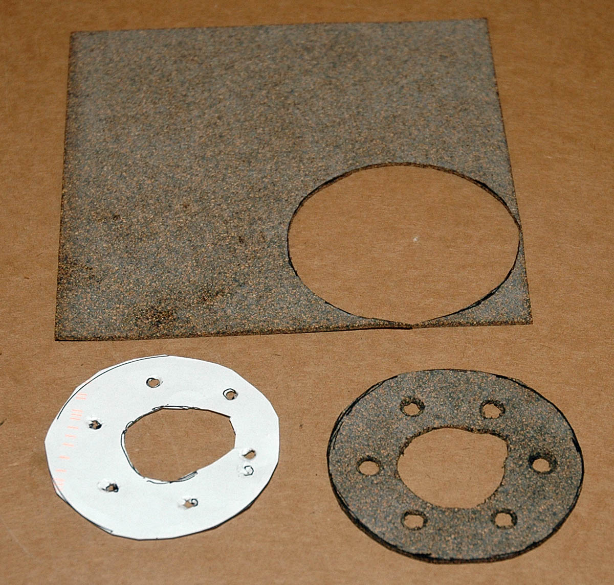
Paper pattern was made to match the new hole-alignment on flange; it is then transferred to cork gasket material.
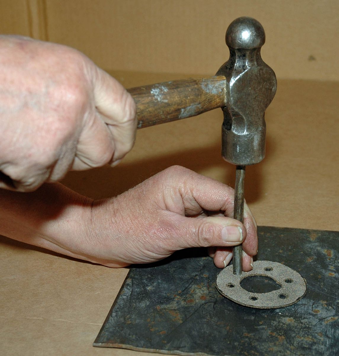
If you don’t have a gasket hole punch then a piece of steel fuel line of the correct size can be used to cut the holes in the cork gasket. Some other gasket materials may be a little tougher to do this with.

Sender was cut to a little less than half of the fuel tank depth and a new hole drilled and tapped for the clamping bracket.

Cut down sender is adjusted to half the depth of the fuel tank and the clamps tightened. Center of float pivot point should be the reference for half the depth.
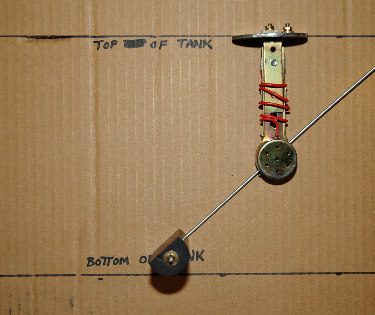
Float is installed in our mockup of the tank and positioned just off the bottom of the tank.

Float is then swung through full travel to determine that it ends its travel just below the top of the tank.

Once the travel of the float through its full swing has been determined the rod can be cut to length and the screw tightened on the pivot shaft.

Sender unit is installed into the tank using the new gasket and appropriate hardware.

Next the fuel pickup tube is screwed into the sender flange.

The finished unit provides for the signal to the fuel gauge and site for the fuel pickup.

Short section of 3/8-inch fuel hose connects tank to steel line routed along the inside face of the right frame rail.

Three-eights inch steel fuel line passes over the rear crossmember and is secured with insulated clamps.

Fuel line continues along the frame rail taking care not to route it too close to any exhaust components. I chose to use a continuous piece of line because I was able do so while the body was off. Some applications might need to join more than one length of line at strategic points to allow for routing in close quarters.


Here is the finished end in the engine compartment where a short fuel hose will complete the connection from the fuel tank to the fuel pump.
Wiring for the gauge chosen will vary depending on the application. Instructions for this are usually included with the gauge package. Your fuel gauge may seem like a minor item until you find yourself out on the open road in the middle of nowhere and without a fuel stop insight. Then you may learn to appreciate this often-overlooked item.